
Arc Protective Systems in Low Voltage Panels
Arc Protective Systems in Low Voltage Panels
Uncategorized
3.10.2018 15:47
3.10.2018 15:47
ELECTRICITY

Protection measures in low-voltage panels are of great importance day by day. The use of intelligent systems has become a necessity in order to keep the systems under energy under sustainable energy. In this context, ease of access after the failure of the system and maintenance works in a short time will provide a great decrease in costs. Another one of the technologies developed with all kinds of risks in mind is the integration of arc termination devices in low voltage panel systems. In this way, in case of any short circuit that may occur in the facility, the main bar system of the panel can be grounded without the formation of an internal arc with the help of sensors and major damages to be caused in the system can be prevented. There are some protection methods developed for operator safety in low voltage panel systems. The most important of these are partitioning, isolation measures and additional protection measures in the panel. For this purpose, different types of protection solutions are emerging with the developing technology. As a necessity of Industry 4.0, 'digitalization' pushes engineering companies to find different solutions within the panels. With the development of new technologies, higher security measures can be taken. DESIGN OF ARK PROTECTION SYSTEMS IN THE PANEL With the developed arc protection system technology, operator safety has been maximized and at the same time, plant maintenance can be carried out in a short time and the cells that are not damaged can be energized quickly. With the panels tested in accordance with IEC 61439, maintenance and use are guaranteed throughout the life of the plant. An internal arc that may occur in low-voltage panels where arc termination systems are used is prevented and mechanically damaging and re-investment costs are prevented. Since the disruptions that will occur due to the power outage may have serious financial consequences, we can say that such systems, which are seen as costing the initial investment, will provide great benefits going forward. As can be seen in the circuit diagram (Figure-1), after the warning to the relay with the help of sensors, mainbar grounding can be done in as little as 3ms and the mainbar supply line is disabled. 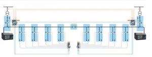 The arc detection system should generally be positioned in accordance with the usage area within the system. During the design of the project, the arc detection relay and the sensor cable line placement between the panels are of great importance in the relevant panels. During the transition between mechanical compartments, the passage of the optical cables without damage and their positioning at the optimum distances on the line is another important issue for the smooth operation of the system. In the case of series connections between sensors to each other, protective measures must be applied in the main bar compartment. In general, it is necessary to cabble between the panels and in the compartments in a protected way over the ground line along the cable line. Otherwise, in the event of a possible short circuit, the sensor may be damaged without transmitting the warning and create an internal arc in the board. Therefore, in this application, which aims to prevent the internal arc and ensure the continuity of energy, the communication elements and design between the devices are of serious importance. Arc Extinguishing Unit and Relay Panel Layout The positioning of arc extinguisher systems in the facility is in a separate panel. All primary and secondary
  devices can be placed in this panel and designed in accordance with the type tests in accordance with the request. At the same time, it can be configured in the panel with protection class up to IP54. Depending on the position of the mainbara, the position of the grounding unit varies and the positioning of the sensors may vary at different main busbar positions. By making phase connections between the grounding unit and the main busbar, it is aimed to absorb the entire load at the time of possible internal arc. In the event of a possible short circuit, the microfiber connection cable that provides communication between the relay and the grounding device can be designed as a maximum of 10 m. For this reason, it is necessary to pay attention to the cable length during the design of the relay on the door in the facility. In the arc protective system, 2 different types of protective measures can be taken. It is possible to install the relay only in accordance with the light-sensitive or light- and current-sensitive project. ARK PROTECTION SYSTEM ELECTRICAL DESCRIPTION AND DETAILS Arc is a combustion event caused by an electrical failure between conductors with different potentials and as a result of a short circuit over the air. The rate of destruction is high compared to other faults. It has serious effects not only on harmful equipment but also on the living things in the environment. It is of great benefit to pay attention to arc protection measures during project design. One of the most important of these is the limitation of the damage caused. Thanks to the fault detection sensors and protection relays installed in various sections, the total destruction on the switchgear is prevented due to the fast opening time of 2ms and the arc extinguishing time of 3 ms, and the failure is limited only to the section where it occurs. As a result, there is no downtime in the whole plant, which prevents long downtime. In addition, selective opening can be performed and only the circuit breaker closest to the fault zone can be opened, which plays a serious role in finding out where the source of error is. Another important benefit is the cost savings. Additional investment costs will arise after an arc failure that may occur. In addition to the initial investment costs, high costs such as the renewal of switchgear, repair of other damages within the facility, etc. will occur. Apart from all these, it is possible for the operator to face a danger to life after a possible internal arc. For this reason, unpredictable penalties and prestige losses will occur. Arc protection system generally consists of arc protection relay, arc extinguishing device and sensing sensors. Arc sensors are connected to the arc protection relay by positioning them in various compartments such as the main busbar, switch or cable compartment. When an error is detected by the sensors, the command to switch on to the nearest switch is sent within 2ms via the protection relay. The switching on time is added to this and a quick intervention to the fault is carried out. The arc extinguisher is designed for a faster arc elimination. To do this, it creates a three-phase low-impedance parallel path to the fault current path and draws the arc fault to the extinguishing unit so that it does not allow the arc to extend to other parts of the board and extinguishes it. The total working time is 3ms to completely eliminate the arc. The rapid activation of the circuit breaker thanks to this protection system prevents the arc from reaching full speed, allowing it to cause less damage to both equipment and workers. The arc damper device design is a system that can be applied up to 100kA and 690V and has been developed using Thompson Coil technology. An example of the arrangement and principle of operation of arc extinguisher, arc relay, arc sensors in a single-input busbar system (Figure 2) is shown below. Here, fault information from the light sensors placed in various compartments to the protection unit and current information from the current transformer on the main line are transmitted to the arc protection relay. Then, from this relay, the command to open the arc extinguisher and circuit breaker is sent.
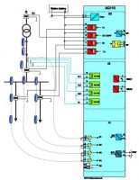
 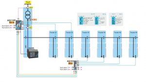 Exemplary Working Principle in Single Entry Systems As stated in the general connection detail of the protection relay, a maximum of 3 sensors are connected in series (Picture-2) and connected to the sensor inputs. The current information from the current transformer is connected to the current inputs of the relay. With the trip relay contacts, the command to open is also sent to the cutters in different positions. (Figure 3) Series connection between sensors Protection relay connection diagram
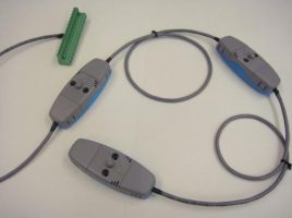
 The light sensors are connected to the arc relay as shown in Picture-3 below and fault information is transmitted. Sensor and Relay Connection
  As a requirement of the working principle, the arc damping device charges itself by being fed over the auxiliary voltage line and informs that it is active in the system with the ready command. In the event that the system is activated in the event of a possible short circuit, the device will warn that it is in the closed position, and in this case, the device must be taken to the open position in 3 stages with the help of a special apparatus as seen in Figure-4. After the device is installed, it charges itself again via the auxiliary voltage line and becomes available in the system again with the ready command. The arc damping device allows it to be tested 100 times and to work under load 2 times. Reinstallation of the Device with Apparatus In today's conditions, where field conditions and costs have become more important than in the past, arc protection, which is a fast protection method in panels, is an effective method. In conditions where industrial applications are more digital and accelerated, it is an effective solution to detect and dampen the arc instantly in the panels. The arc damping system, which can be selected in low-voltage panels, also serves very effectively in meeting this need in industrial facilities. In general, the benefits of arc protection systems can be summarized in the following items.
The arc detection system should generally be positioned in accordance with the usage area within the system. During the design of the project, the arc detection relay and the sensor cable line placement between the panels are of great importance in the relevant panels. During the transition between mechanical compartments, the passage of the optical cables without damage and their positioning at the optimum distances on the line is another important issue for the smooth operation of the system. In the case of series connections between sensors to each other, protective measures must be applied in the main bar compartment. In general, it is necessary to cabble between the panels and in the compartments in a protected way over the ground line along the cable line. Otherwise, in the event of a possible short circuit, the sensor may be damaged without transmitting the warning and create an internal arc in the board. Therefore, in this application, which aims to prevent the internal arc and ensure the continuity of energy, the communication elements and design between the devices are of serious importance. Arc Extinguishing Unit and Relay Panel Layout The positioning of arc extinguisher systems in the facility is in a separate panel. All primary and secondary devices can be placed in this panel and designed in accordance with the type tests in accordance with the request. At the same time, it can be configured in the panel with protection class up to IP54. Depending on the position of the mainbara, the position of the grounding unit varies and the positioning of the sensors may vary at different main busbar positions. By making phase connections between the grounding unit and the main busbar, it is aimed to absorb the entire load at the time of possible internal arc. In the event of a possible short circuit, the microfiber connection cable that provides communication between the relay and the grounding device can be designed as a maximum of 10 m. For this reason, it is necessary to pay attention to the cable length during the design of the relay on the door in the facility. In the arc protective system, 2 different types of protective measures can be taken. It is possible to install the relay only in accordance with the light-sensitive or light- and current-sensitive project. ARK PROTECTION SYSTEM ELECTRICAL DESCRIPTION AND DETAILS Arc is a combustion event caused by an electrical failure between conductors with different potentials and as a result of a short circuit over the air. The rate of destruction is high compared to other faults. It has serious effects not only on harmful equipment but also on the living things in the environment. It is of great benefit to pay attention to arc protection measures during project design. One of the most important of these is the limitation of the damage caused. Thanks to the fault detection sensors and protection relays installed in various sections, the total destruction on the switchgear is prevented due to the fast opening time of 2ms and the arc extinguishing time of 3 ms, and the failure is limited only to the section where it occurs. As a result, there is no downtime in the whole plant, which prevents long downtime. In addition, selective opening can be performed and only the circuit breaker closest to the fault zone can be opened, which plays a serious role in finding out where the source of error is. Another important benefit is the cost savings. Additional investment costs will arise after an arc failure that may occur. In addition to the initial investment costs, high costs such as the renewal of switchgear, repair of other damages within the facility, etc. will occur. Apart from all these, it is possible for the operator to face a danger to life after a possible internal arc. For this reason, unpredictable penalties and prestige losses will occur. Arc protection system generally consists of arc protection relay, arc extinguishing device and sensing sensors. Arc sensors are connected to the arc protection relay by positioning them in various compartments such as the main busbar, switch or cable compartment. When an error is detected by the sensors, the command to switch on to the nearest switch is sent within 2ms via the protection relay. The switching on time is added to this and a quick intervention to the fault is carried out. The arc extinguisher is designed for a faster arc elimination. To do this, it creates a three-phase low-impedance parallel path to the fault current path and draws the arc fault to the extinguishing unit so that it does not allow the arc to extend to other parts of the board and extinguishes it. The total working time is 3ms to completely eliminate the arc. The rapid activation of the circuit breaker thanks to this protection system prevents the arc from reaching full speed, allowing it to cause less damage to both equipment and workers. The arc damper device design is a system that can be applied up to 100kA and 690V and has been developed using Thompson Coil technology. An example of the arrangement and principle of operation of arc extinguisher, arc relay, arc sensors in a single-input busbar system (Figure 2) is shown below. Here, fault information from the light sensors placed in various compartments to the protection unit and current information from the current transformer on the main line are transmitted to the arc protection relay. Then, from this relay, the command to open the arc extinguisher and circuit breaker is sent. Exemplary Working Principle in Single Entry Systems As stated in the general connection detail of the protection relay, a maximum of 3 sensors are connected in series (Picture-2) and connected to the sensor inputs. The current information from the current transformer is connected to the current inputs of the relay. With the trip relay contacts, the command to open is also sent to the cutters in different positions. (Figure 3) Series connection between sensors Protection relay connection diagram The light sensors are connected to the arc relay as shown in Picture-3 below and fault information is transmitted. Sensor and Relay Connection As a requirement of the working principle, the arc damping device charges itself by being fed over the auxiliary voltage line and informs that it is active in the system with the ready command. In the event that the system is activated in the event of a possible short circuit, the device will warn that it is in the closed position, and in this case, the device must be taken to the open position in 3 stages with the help of a special apparatus as seen in Figure-4. After the device is installed, it charges itself again via the auxiliary voltage line and becomes available in the system again with the ready command. The arc damping device allows it to be tested 100 times and to work under load 2 times. Reinstallation of the Device with Apparatus In today's conditions, where field conditions and costs have become more important than in the past, arc protection, which is a fast protection method in panels, is an effective method. In conditions where industrial applications are more digital and accelerated, it is an effective solution to detect and dampen the arc instantly in the panels. The arc damping system, which can be selected in low-voltage panels, also serves very effectively in meeting this need in industrial facilities. In general, the benefits of arc protection systems can be summarized in the following items.- Reduction of maintenance costs
- Being a fast and effective protection method
- Operator safety
- Sustainability of energy
- Re-commissioning of the system after possible arc failure
- Prevention of investment costs that will occur again after the failure
- Increasing productivity in the industrial plant
- Easy detection of the fault in the system and quick intervention
- The advantage of easy installation of the system
-
A+Buyut
-
A-Kucult
 SİZİN DÜŞÜNCELERİNİZ?

Uncategorized
ELEKTRİK VE ENERJİ SEKTÖRÜMÜZ DUBAİ'DE MAHSUR KALDI
Uncategorized
Doğanateş Olarak Sektörümüzde Önemli Başarılara İmza Attık Atmaya da Devam Edeceğiz
Uncategorized
THE PLACE OF NYTRO BIO 300X IN SUSTAINABLE TRANSFORMER PRODUCTION
Uncategorized
Schneider Electric Turkey Agreed With FullCharger For Charging Stations
Uncategorized
OSRAM and ams continue their way as a single company
Uncategorized
Sigma Electric 2022 Business Partners Organization Took Place in TRNC
Uncategorized
BAŞOĞLU'S CABLE THAT CAN WORK UNDER HEAT AND FLAME IS AT HANNOVER MESSE
Uncategorized
ABB partners with Samsung Electronics for smart building technology
Uncategorized
Turkey's fastest electric vehicle charging stations are coming
Uncategorized
Adaptation to New and Changing Demands in Production is a Must
Uncategorized
Prysmian Group MEAT Region Marketing and Communications Director Tamer Yavuztürk
Uncategorized
DEKO AUTOMATION ELECTRICITY
Uncategorized
Aktif and Nuventura Sign Agreement for SF6 Gas-Free Cell Production
Uncategorized
Export Giants of Electrical and Electronics Sector Awarded
Uncategorized
Sigma Electric's export offensive
Uncategorized
Active e-commerce site is online!
Uncategorized
Eaton Turkey - Üçay Signs Partnership Agreement with Group
Uncategorized
Eaton Announces 'Energy Producing Buildings' Approach in Turkey
Uncategorized
Borsan's Production Facility Investment in Togo, African Country
Uncategorized
Electricity Turkey Magazine August 2021
Uncategorized
INTERNATIONAL AWARD TO YEDAŞ
