


What is LV Current Transformer?
Current transformers are the circuit elements that reduce the current passing through power lines and electrical circuits to a level that measuring instruments, meters, relays and other devices working with similar techniques can measure without damage and isolate these devices against high currents.
It is not possible to measure the current passing through the line directly with measuring instruments after a certain amperage level. Current transformers are generally used in measurement and protection processes. A user who does not want to use a current transformer at high current values will need large-sized measuring instruments and protection relays to measure the current values. Such a situation would be both costly and dangerous. Depending on the hardware features of the measuring instruments, they can be directly connected to the circuit to be measured up to a certain ampere value. For higher current values, the current transformer is connected to the circuit before the measuring instruments and the measuring instrument is insulated from this high current value. Thus, it is possible to measure at high current values.
Current transformers are produced as single phase. A phase cable or bus for the circuit to be measured is passed through the window of the current transformer in such a way that the current direction is from P1 to P2. The phase and neutral terminals of the measuring instrument are connected to the secondary ends of the current transformer. Since the current direction will be from P1 to P2, the active end will be S1, and this secondary end is connected to the phase terminal of the measuring instrument. The S2 end is connected to the neutral terminal of the measuring instrument. The current conversion rate of the measuring instrument is set and the desired circuit is energized.
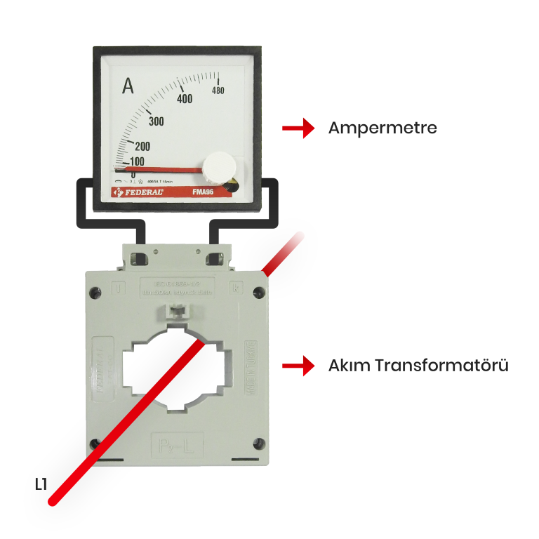 Figure-2: Measuring Tool Connection
How Does It Work?
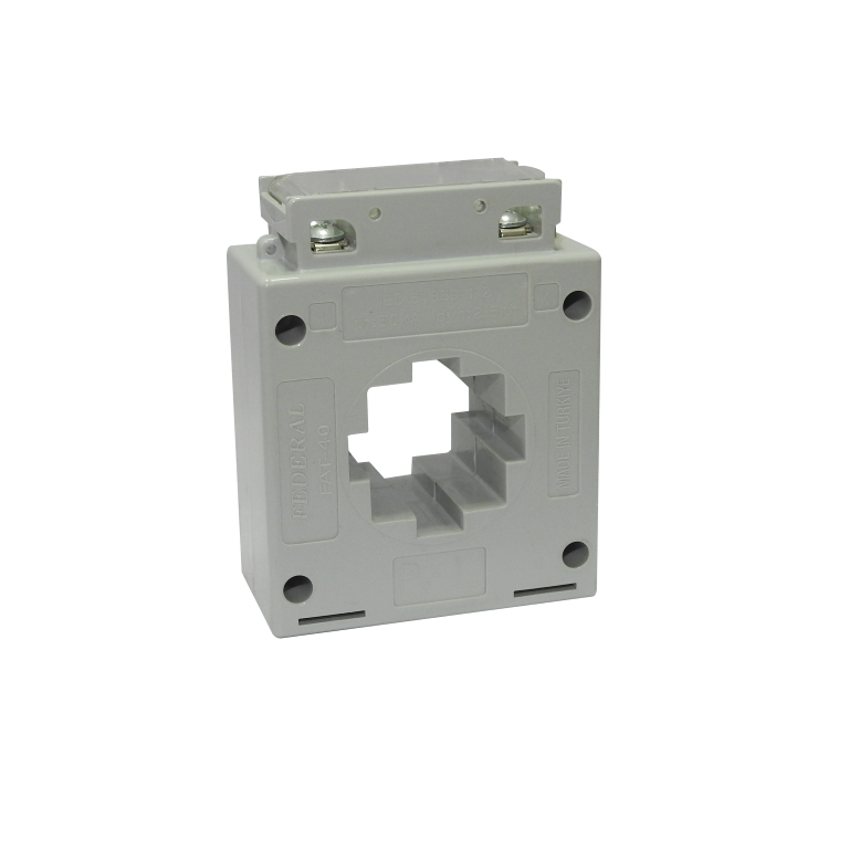
Current transformers are circuit elements that convert high primary currents into low secondary currents according to conversion rates. Current transformers basically consist of magnetic iron core, secondary windings wrapped on the core and secondary terminals for the windings to be connected to the measuring instrument.
In busbar models, the primary winding is connected in series to the magnetic iron core. The secondary windings are wound in the opposite direction to the primary windings. Models with windows of LV current transformers do not have primary windings. The cable or busbar of the circuit to be measured is passed through the window of the transformer. The primary charge occurs through the magnetic field generated by the current-carrying conductor. The current passing through the primary causes a magnetic flux flow on the core by creating a magnetic field on the magnetic core. This magnetic flux on the core causes voltage to be induced in its secondary windings. If the secondary windings are connected to the load (measuring instrument, etc.), current will start to flow from the secondary windings to the load and the feeding of the measuring instrument will take place.
What are the Considerations?
The current passing through the secondary circuit creates a magnetic flux on the magnetic core in the opposite direction due to the reversal direction of the winding (according to the primary current). This magnetic flux balances the magnetic flux generated by the current passing through the primer. For this reason, the secondary windings of current transformers must be short-circuited with a measuring instrument or load. If it is not short-circuited, a magnetic flux in the opposite direction will not occur and the magnetic flux generated by the primary current on the core will not be balanced. This may lead to increased copper losses in the magnetic iron core, thereby overheating of the core and failure of the current transformer. In addition, if the secondary ends are not short-circuited, the magnetic flux generated by the primary current on the core causes voltage to be induced at the secondary ends and voltage increase in direct proportion to the number of secondary windings. Voltage rise at the secondary ends can cause the winding insulation to deteriorate and pose a vital risk to the field worker.
 Image-3: Twin Screw Secondary Terminals
Federal Current Transformer
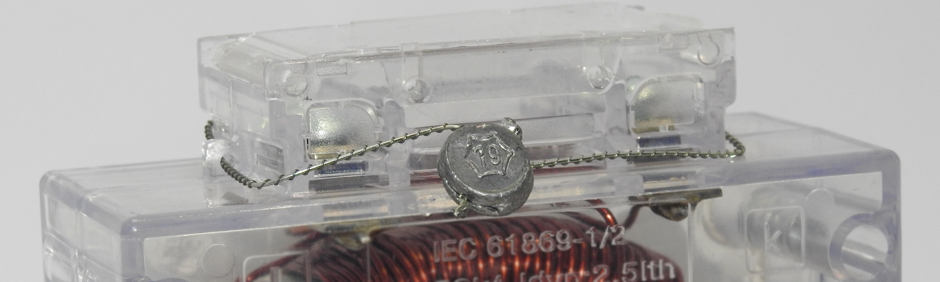 Image-4: Sealing
 SİZİN DÜŞÜNCELERİNİZ?
